Wireless Solutions
Base Station Panel Antennas — 2G / 3G / 4G / 5G
The ZTT panel-antenna catalogue covers eleven product series spanning every commercial cellular band from 698 MHz to 3600 MHz. Every model uses ±45° dual polarization, ≥28 dB port isolation, ≤1.5 VSWR, ≤-107 dBm IMD @ 2×43 dBm and integrates an AISG RET RCU. Common mechanical specifications: 50 Ω impedance, DC-ground lightning protection, FRP or UPVC radome in gray, ⌀50–⌀115 mm pole mounting and −40 °C to +70 °C operating range. The series are organized by frequency band and port count, from single-band 8090 (824–960 MHz) 4-port antennas through 6090-1727 six-band multi-radio antennas and 4G/5G TDD antennas up to 3.3–3.6 GHz.
Features & Characteristics
- ▪Eleven distinct antenna series covering 698 MHz to 3600 MHz.
- ▪Every model uses ±45° dual polarization and integrated AISG RET RCU.
- ▪Port isolation ≥ 28 dB (intra-band ≥ 26 dB, inter-band ≥ 80 / 90 dB in multi-band models).
- ▪F/B ratio ≥ 25 dB and first-sidelobe suppression ≤ −15 dB across the range.
- ▪VSWR ≤ 1.5 and IMD ≤ −107 dBm @ 2×43 dBm.
- ▪50 Ω impedance; 7/16 DIN, 4.3-10 DIN or N-Female connectors depending on family.
- ▪Max input power 250 W (1721 / 1727 series) or 300 W (8090 / 6090 series).
- ▪FRP or UPVC gray radome; DC-ground lightning protection.
- ▪Pole mounting ⌀50 – ⌀115 mm; operating temperature −40 °C to +70 °C.
- ▪Mechanical downtilt 0° – 25° depending on model.
Applications
- ▪Macro-cell base station coverage for 2G / 3G / 4G / 5G networks.
- ▪Single-band deployments (8090, 6090, 1721, 1727 series).
- ▪Multi-band sector consolidation (8090-1721, 7090-1727, 6090-1721, 6090-1727 series).
- ▪5G NR TDD deployments in the 1885–2675 MHz and 3.3–3.6 GHz bands.
- ▪Combined FDD + TDD multi-radio sites where a single radome hosts 4G FDD and 5G TDD ports.
- ▪Small-cell densification with the compact 9-port N-female radome.
Technical specifications
- Number of product series
- 11 (see model tables below)
- Total frequency coverage
- 698 MHz to 3600 MHz
- Polarization
- ±45° dual polarization on every model
- Gain (typical)
- 11 dBi (small cell) to 17.5 dBi (6090 FET)
- Horizontal beamwidth options
- 65° / 90° / 100°
- Isolation
- Intra-band ≥ 26 dB, inter-band ≥ 80 dB (≥ 90 dB in specific multi-band pairs)
- XPD
- Main direction ≥ 15 dB, sector ±60° ≥ 10 dB (≥ 8 dB on some 4-port models)
- 1st sidelobe suppression
- ≤ −15 dB
- F/B ratio
- ≥ 25 dB
- VSWR
- ≤ 1.5
- IMD
- ≤ −107 dBm @ 2×43 dBm
- Impedance
- 50 Ω
- Max. input power
- 250 W (1721/1727) — 300 W (8090/6090)
- RET
- Integrated RCU (AISG 2.0 on multi-band 6090 series)
- Lightning protection
- DC Ground on every model
- Connectors
- 7/16 DIN Female, 4.3-10 DIN Female, or N Female (small cell)
- Radome material
- FRP or UPVC, gray
- Mounting hardware
- ⌀50 – ⌀115 mm pole mount
- Mechanical downtilt
- 0° – 25° (model dependent)
- Operating temperature
- −40 °C to +70 °C
1. 8090 series (824–960 MHz)
| Frequency (MHz) | Gain (dBi) | Connectors | Size (mm) | Weight (kg) |
|---|---|---|---|---|
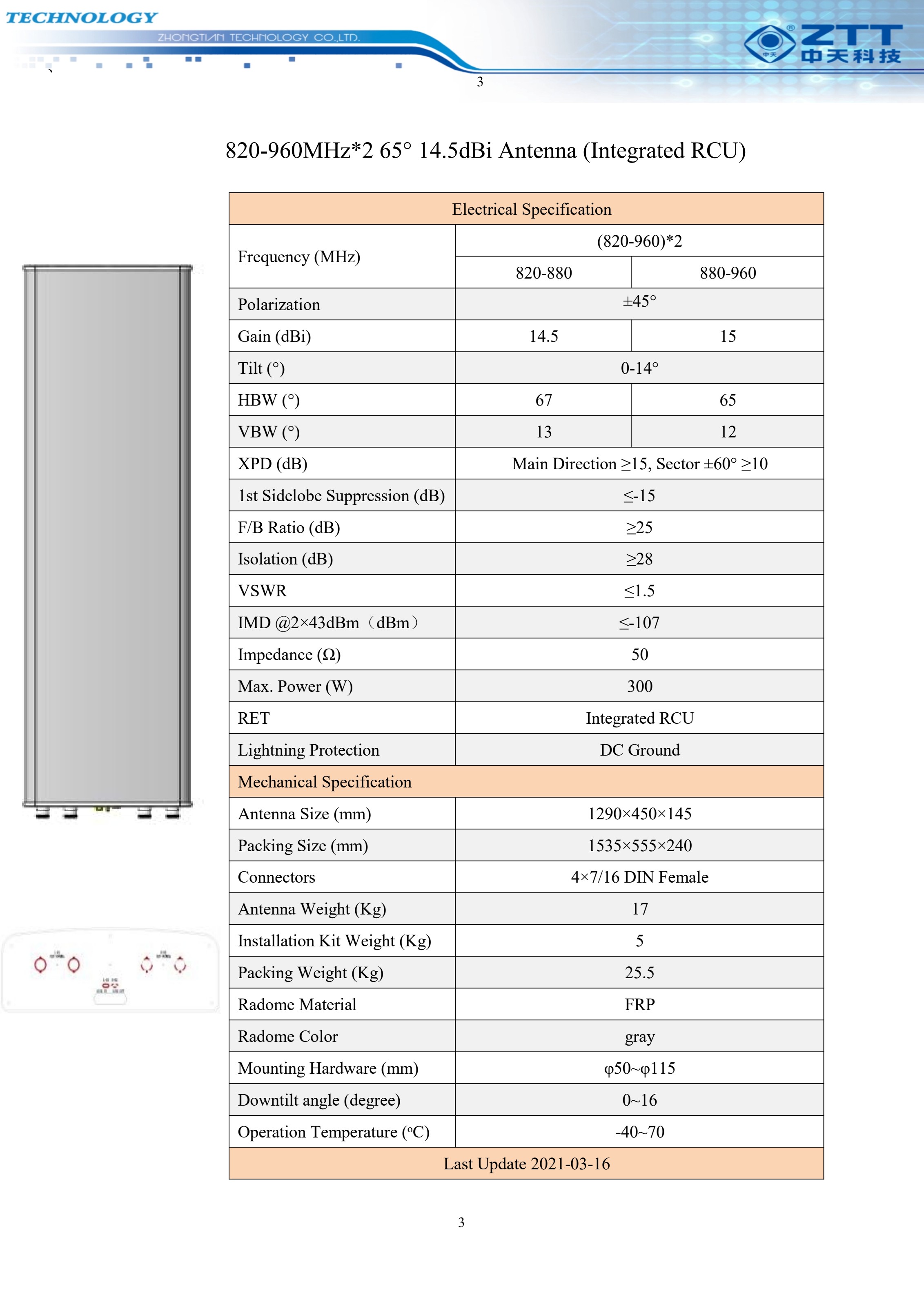
| (820–960)*2 | 14.5 / 15 | 4×7/16 DIN Female | 1290×450×145 | 17 |
| (820–960)*2 | 16 / 16.2 | 4×7/16 DIN Female | 1780×450×145 | 23.5 |
2. 6090 series (698–960 MHz)
| Frequency (MHz) | Gain (dBi) | Connectors | Size (mm) | Weight (kg) |
|---|---|---|---|---|
| (703–803)*2 / 824–884 / (905–960)*2 | 15.7 / 16 / 16.7 | 10×4.3/10 DIN Female | 2500×500×196 | 50.5 |
| (703–768)*2 / (738–803)*2 / 824–884 / (905–960)*2 | 15.7 / 15.8 / 16 / 16.7 | 14×4.3/10 DIN Female | 2640×630×175 | 60.5 |
| 698–960 (FET, 0°) | 16.8 / 17.2 / 17.5 | 2×7/16 DIN Female | 2565×295×145 | 20.7 |
3. 1721 series (1710–2170 MHz)
| Frequency (MHz) | Gain (dBi) | Connectors | Size (mm) | Weight (kg) |
|---|---|---|---|---|
| (1710–2170)*2 | 14.5 | 4×7/16 DIN Female | 635×278×138 | 6.35 |
| (1710–2170)*2 | 17 | 4×7/16 DIN Female | 1165×278×138 | 10.2 |
| (1710–2170)*3 | 17 | 6×7/16 DIN Female | 1295×398×141 | 14.5 |
| (1710–2170)*4 | 14.5 | 8×7/16 DIN Female | 800×500×115 | 11.7 |
| (1710–2170)*4 | 17 | 8×7/16 DIN Female | 1350×500×115 | 18.2 |
4. 1727 series (1710–2690 MHz)
| Frequency (MHz) | Gain (dBi) | Connectors | Size (mm) | Weight (kg) |
|---|---|---|---|---|
| (1710–2690)*2 | 16.5 / 16.8 / 17.1 | 4×4.3/10 Female | 1350×320×110 | 13 |
5. 8090-1721 series (dual-band 820–960 / 1710–2170 MHz)
| Configuration | Gain (dBi) | Series |
|---|---|---|
| 820–960 / 1710–2170 | 14.5 / 17 | Integrated RCU |
| 820–960 / 1710–2170 | 16 / 17 | Integrated RCU |
| 820–960 / (1710–2170)*2 | 14.5 / 17 | Integrated RCU |
| 820–960 / (1710–2170)*2 | 16 / 17 | Integrated RCU |
| 820–960 / (1710–2170)*3 | 14.5 / 17 | Integrated RCU |
| 820–960 / (1710–2170)*3 | 16 / 17 | Integrated RCU |
| (820–960)*2 / (1710–2170)*2 | 14.5 / 17 | Integrated RCU |
| (820–960)*2 / (1710–2170)*2 | 16 / 17 | Integrated RCU |
| (820–960)*2 / (1710–2170)*3 | 14.5 / 17 | Integrated RCU |
| (820–960)*2 / (1710–2170)*3 | 16 / 17 | Integrated RCU |
| (820–960)*2 / (1710–2170)*4 | 14.5 / 17 | Integrated RCU |
| (820–960)*2 / (1710–2170)*4 | 16 / 17 | Integrated RCU |
| (820–880)*2 / 900–960 / (1710–2170)*4 | 14.5 / 14.7 / 17 | Integrated RCU |
6. 7090-1727 series (dual-band 790–960 / 1710–2690 MHz)
| Configuration | Gain (dBi) | Series |
|---|---|---|
| 790–960 / 1710–2690 | 16 / 17 | Integrated RCU |
7. 6090-1721 series (tri-band 703–1830 MHz)
| Configuration | Gain | Series |
|---|---|---|
| (703–798)*2 / (885–960)*2 / (1710–1830)*2 | 65° | Integrated RCU |
8. 6090-1727 series (multi-band 694–2690 MHz)
| Configuration | Gain | Series |
|---|---|---|
| 694–960 / 1710–2690 / 1710–2170 / 2490–2690 / 1710–1880 / 1920–2690 | Multi-band | Integrated RCU |
| 694–862 / 880–960 / 1710–2170 / (1710–2690)*2 / 2490–2690 | Multi-band | Integrated RCU |
9. 4G & 5G TDD series (1885–2675 MHz)
| TDD Bands (MHz) | Beamwidth | Gain (dBi) | Series |
|---|---|---|---|
| 1885–1915 / 2010–2025 | — | 13.5 / 14.5 | TDD |
| 1885–1920 / 2010–2025 / 2515–2675 | 100° / 90° / 65° | 11 / 12 / 13.5 | TDD |
| 1885–1920 / 2010–2025 / 2515–2675 | 100° / 90° / 65° | 12.5 / 13.5 / 14.5 | TDD |
| 1885–1920 / 2010–2025 / 2515–2675 | 100° / 90° / 65° | 13 / 13.5 / 15 | TDD |
| (3300–3600)*4 | 65° | 16.5 (2–12° tilt) | TDD (Integrated RCU) |
10. TDD + FDD series (combined 4G/5G platforms)
| Description | Notes |
|---|---|
| Combined TDD/FDD panel antennas — pages 44–48 of the catalogue | Full multi-band configurations combining the 1727 / 1721 FDD ports with the 1885–2675 MHz TDD ports on a single radome |
11. Small Cell series
| Description | Connectors | Size (mm) | Weight (kg) |
|---|---|---|---|
| Small Cell panel antenna (multi-port compact radome) | 9×N Female | 955×290×118 | 8.8 |
Need a specification we don't list?
We source technical products on request. Send us your specification sheet and we will respond with sourcing options and lead times.